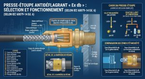
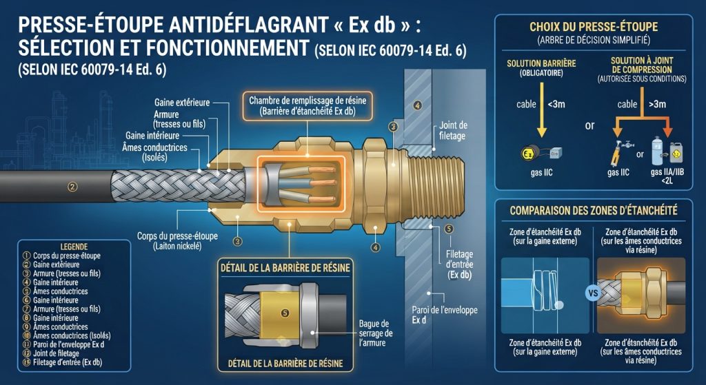
The changes to the selection criteria for cable glands used in “Ex d” (or Ex db) explosion-proof equipment represent one of the most significant and most debated changes in the latest revisions to the IEC 60079-14 standard.
The crux of the issue with “Ex d” is to prevent the cable gland or the interior of the cable from becoming a pathway for the propagation of a flame or overpressure to the outside in the event of an internal explosion. Regulations have changed significantly to clarify the choice between a standard cable gland (with a compression ring) and a barrier-type cable gland (with a filling compound or resin).
Here is the history and how this evolution has unfolded, leading up to the brand-new Version 6.0 (2024).
The History of Selection Criteria
1. The Old Model (Before 2014): Based on Volume and Gas
The choice was based entirely on the envelope's characteristics:
- The volume of the box was measured (critical threshold: 2,000 cm³).
- We were looking at the gas group (IIA, IIB, IIC).
- If the volume was large or the gas was highly unstable (IIC), a barrier gland was required.
2. The Shift to Edition 5.0 (2013): The Famous “3-Meter Test”
The standard has shifted its focus from the enclosure to the cable structure (since the gaps between the internal conductors can allow gases and flames to spread). A decision tree has introduced complex criteria:
- The cable had to be round, compact, and extruded.
- If the cable was less than 3 meters long, or if it was not perfectly “compact” (risk of internal voids), the barrier-type cable gland was always required, which significantly increased the complexity of installation projects.
The Publishing 6.0 Revolution (2024 / 2025)
Edition 6.0 of IEC 60079-14 completely revises the method using a new, mandatory decision tree that takes into account gas type, length, enclosure volume, and the actual physical properties of the cable.
1. Transfer of Responsibility (From the Installer to the Designer)
This is a major organizational change. Under the previous edition, the choice of cable gland was often made on-site by the installer when cutting the cable. With Edition 6, the selection requires knowledge of the gas group, the exact volume of the enclosure, and the cable’s technical specifications: responsibility for selection is now officially transferred to the design engineer or engineering department.
2. The New Rules of the Decision Tree
The new standard outlines a process with four key milestones:
- For unstable gas groups (IIC and IIB + H₂): If the cable is less than 3 meters long, the barrier-type cable gland remains strictly mandatory.
- For standard gas groups (IIA and IIB): If the cable is at least 0.5 meters long and the volume of the associated enclosure is less than 2,000 cm³, a standard compression-ring cable gland (non-barrier type) is directly permitted.
3. The Introduction of Annex C (Cable Pressure Test)
If the volume of the enclosure exceeds 2,000 cm³ (or if it is unknown) for IIA/IIB gases, the designer can no longer simply “guess” whether the cable is compact.
- The former recommendation (Appendix E) becomes a strict and binding regulation (Appendix C).
- It introduces a gas migration test (underwater pressure test).
- If the cable passes the test in Annex C (no air leakage through the strands), a standard compression-seal cable gland is acceptable. If it fails the test or is not tested, a barrier-type cable gland is required.
4. The Issue of Single-Conductor Cables Finally Clarified
Edition 6 corrects a long-standing technical inconsistency: on a single-conductor (unipolar) cable, applying resin/barrier directly to the single conductor provided no additional safety compared to a standard elastomer seal. The decision tree requirements now include logical flexibility for these types of cables.
When should the cable gland mounting module be installed?
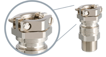
In ATEX (Explosive Atmospheres) regulated areas, safety depends on strict compliance with the EN/IEC 60079-14 installation standard. In this context, the use of a mechanical retention device such as an external tie-down module (often supplied with clamping brackets) is legally and technically mandatory in the following scenarios:
1. Failure to anchor the cable within 300 mm
The ATEX EN 60079-14 standard requires that any cable entering an explosion-proof (Ex d) or increased safety (Ex e) enclosure be securely fastened to prevent external mechanical tension from compromising the internal seal or pulling the wires out of the terminal blocks (which would create a spark capable of causing an explosion).
- If the cable is not securely fastened to a cable tray or with a cable tie within 300 mm of the cable gland, it must be secured directly to the cable gland using a dedicated securing module.
2. The use of non-armored cables (without braiding or strapping)
Standard cable glands for non-armored cables (such as the ADE 1F series) provide a seal by compressing the rubber ring, but their pure mechanical retention force is sometimes insufficient to pass the rigorous pull-out tests required by ATEX certification (particularly for large diameters). The external clamping module compensates for this weakness by physically clamping the cable.
3. “X”-certified cable glands (Special Conditions of Use)
When a cable gland model has a certification number ending with the letter “X” (for example, a type examination certificate such as LCIE 97 ATEX 6006 X), this means that its original certification includes restrictions.
- Very often, condition “X” specifies that the equipment has been tested only for a low risk of mechanical impact or that it does not meet the anchoring function requirement. The installer is therefore required by regulation to add the anchoring module accessory so that the entire system is deemed compliant during the initial inspection of the installation.
4. Equipment Subject to Vibrations or Movement
Even at a distance of less than 300 mm from a mounting surface, if the ATEX cable gland is attached to dynamic equipment (electric motor, compressor, grinder, or an area where mobile machinery passes), the risk of the cable jacket slipping due to continuous vibrations requires the installation of a securing module to lock the connection in perfect alignment.
Determination and Validation of the ADF Connection Cable in Accordance with Annex C
The validity and adequacy of the evidence depend entirely on the technical documentation provided by the cable manufacturer or by an independent testing organization.
Under the revised version of IEC 60079-14 (6th edition), the guidelines on gas migration through cables (formerly Annex E) have become the mandatory pressure test specified in Annex C. This test verifies whether a cable’s internal structure is sufficiently leak-tight to prevent explosive gases from migrating.
What is “reliable and sufficient evidence”?
According to industry compliance protocols, the level of evidence is classified based on its source:
- The "Excellent" (Highly Reliable) Level: A type test report or certificate issued by an independent, accredited third-party laboratory confirming that the exact cable model meets the parameters specified in Annex C.
- The minimum (acceptable) requirement: An official and verifiable test report or a declaration of conformity issued directly by the manufacturer’s internal quality control department.
Please note: A simple visual inspection or a standard technical data sheet stating that the cable is “gas-tight” is not considered sufficient proof, as this term is not regulated.
Technical Validation Criteria (Appendix C)
To determine whether your evidence is technically valid, the test report in your possession must demonstrate compliance with the following criteria:
- Initial pressure: A low pressure of 300 pascals (Pa) is applied inside a cable sample.
- Duration: Pressure is measured during a strict 5-second window.
- Passing threshold: The pressure drop must not exceed 150 pascals (or 50%) during these 5 seconds.
If the document shows a drop of more than 150 Pa, the cable fails the test.
When is this evidence essential?
In areas at risk of explosion (Ex d enclosure), proof of compliance with Annex C is required before standard cable glands with sealing rings (non-barrier type) may be used:
- Gas Groups IIA / IIB: Required if the cable is at least 0.5 meters long and the volume of the enclosure is 2,000 cm³ or greater (or unknown).
- Gas Groups IIC / IIB + H₂: Required if the cable length is 3 meters or longer.
In conclusion: If you do not have an official test report validating the 5-second/300 Pa test for the exact model number of your cable, you do not have sufficient evidence. In the absence of this document, Ex inspectors will require the use of a cable gland with a sealing barrier (resin).