In heavy industry, high-power inverters, medium-voltage motors, and transformers are subjected to extreme thermal stresses. Monitoring their temperature is essential for safety. However, installing a sensor on a metal part carrying a potential of several kilovolts (kV) requires perfect control of electrical insulation.
In an industrial setting, a failure in insulation doesn’t just mean a burned-out component—it can cause a destructive electric arc (arc flash), a cabinet fire, or an operator to be electrocuted.
Here are the design and insulation recommendations based on current industry standards.
The Three Pillars of Industrial Safety: Impact, Arc, and Continuity
In industrial power electronics, the design of thermal management must eliminate three major risks:
- Risk of electric shock: Maintenance personnel or operators must never come into contact with high voltage through the chassis or control interfaces (screens, HMIs, buttons).
- Flash Arc (Electric Arc): A breakdown in the sensor’s insulation can trigger an electric arc through the air. In an industrial setting, the energy available upstream can turn this arc into a devastating thermal explosion.
- Fail-Safe Mode: If the sensor is damaged by an overload or mechanical stress, the data acquisition system must immediately detect the open circuit (or short circuit) and switch the system to fail-safe mode (emergency shutdown).
The Regulatory Framework: The Pillars of Industrial Design
To verify the compliance of a thermal measurement chain on components at different potentials, your design must be based on several major international standards:
The primary standard: CEI / IEC 60664-1
This standard defines the coordination of equipment insulation in low-voltage systems (up to 1,000 V AC and 1,500 V DC). It requires the precise calculation of two parameters:
- AirClearance: To prevent an arc from forming in the air, based on the peak voltage and the overvoltage category (CAT II, III, or IV).
- Creepage distance: To prevent current from flowing along the surface of insulating materials, which is heavily influenced by the degree of contamination in industrial environments (conductive dust, moisture). In manufacturing, designs are generally based on Contamination Class 2 (laboratory/sealed enclosure) or 3 (industrial workshop).
Machine and Functional Safety: ISO 13849-1 and IEC 61508
If temperature measurement is integrated into a safety loop (for example, to cut off power to a motor in the event of overheating), the sensor and its data acquisition system must meet Performance Level (PL r) or Safety Integrity Level (SIL) requirements.
Design Recommendations and Insulation Architectures
To ensure maximum industrial safety, the architecture must be based on the dual-barrier principle.
[Élément sous Tension (ex: Jeu de barres 1kV)]
       │
[BARRIÈRE 1 : Isolation physique / Céramique ou TIM]
       │
[Capteur de température (ex: PT100 blindée)]
       │
[BARRIÈRE 2 : Isolation galvanique / Optique ou Magnétique]
       │
[Automate (API) / Système de contrôle (Basse Tension 24V)]
Step 1: Physical Galvanic Isolation (At the Point of Contact)
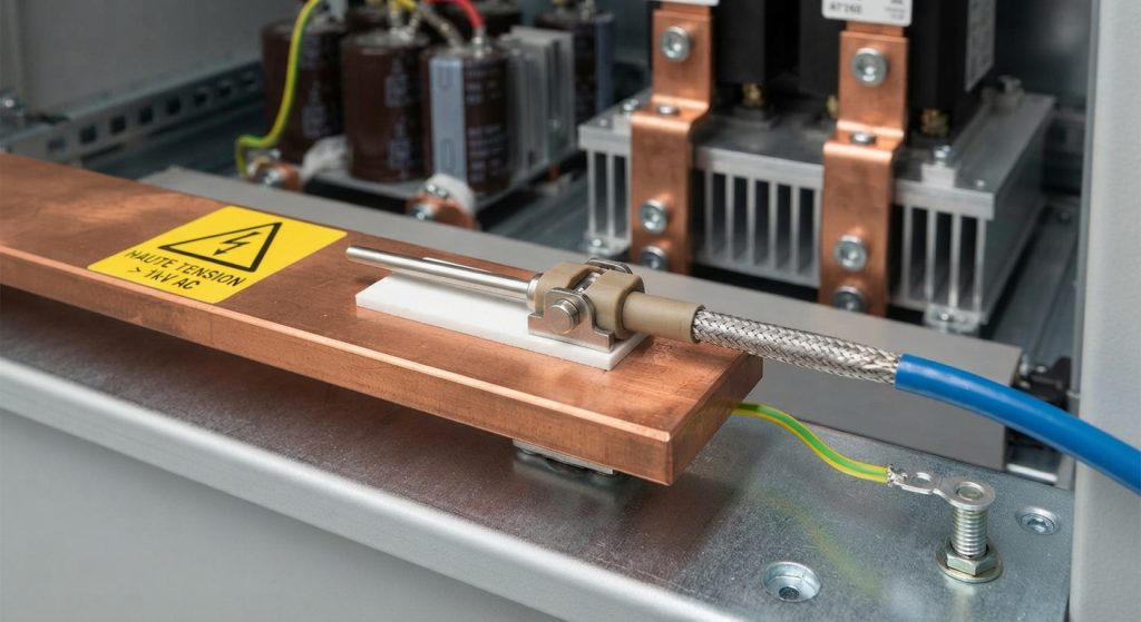
- Thermal interface materials: Use mica sheets, alumina, aluminum nitride, or ceramic-filled elastomers. They conduct heat but block electrical current.
- High-performance heat-shrink tubing: For sensor wires, choose PTFE (Teflon) or Kynar instead of standard PVC. They offer much higher dielectric strength despite their thin wall thickness.
- Sheathed PT100/PT1000 Probes: Choose probes housed in protective sleeves or casings that are insulated from the active element by ceramic rings (alumina or silicon nitride). These materials can withstand breakdown voltages of over 10 kV while maintaining excellent thermal conductivity.
- Electromagnetic Shielding (Faraday Cage): Rapid voltage changes (dV/dt) across power components induce common-mode currents through the sensor’s parasitic capacitance. It is essential to use shielded cables and to connect the shield to the protective earth (PE) at the entry point of the measurement cabinet to divert these parasitic currents before they reach the electronics.
Step 2: Signal and Power Isolation (Cabinet Side)
- Isolated Measurement Converters (DIN-Rail Transmitters): Never connect a probe’s wires directly to the analog input cards of an industrial controller (PLC) without an isolation transmitter. These modules (supplied by industrial manufacturers) provide proven galvanic isolation (often 2.5 kV to 4 kV AC continuous) between the sensor input, the analog output (4–20 mA / 0–10 V), and the 24 V power supply.
- The Ultimate Solution: Optical Isolation: For very high-voltage environments (railway traction inverters, distribution networks), transmitters are used that convert the temperature signal into a light signal. The data stream travels through a plastic or silica optical fiber, providing inherently infinite isolation and total immunity to electromagnetic interference (EMI).
4. Maintenance, Testing, and Aging: Ensuring Safety Over Time
Thermal and electrical insulation that performs well on the first day can deteriorate in an industrial environment.
- The phenomenon of partial discharge: Under high direct or pulsed voltage, microbubbles of air trapped in resins or thermal insulators are subjected to invisible micro-arcs. Over time, this erodes the insulator. Materials certified as “partial discharge-free” for the operating voltage must be selected.
- In-Production Type Tests (Dielectric Test): Each system must undergo a dielectric strength test (“Hi-Pot” test) during manufacturing, by applying a standardized overvoltage (e.g., 2x Uservice + 1000 V) for one minute between the sensor leads and the chassis, to verify that no breakdown occurs.
- Periodic Insulation Testing: During maintenance shutdowns, measuring the insulation resistance (using a megohmmeter at 500 V or 1,000 V) between the sensor circuit and ground helps detect premature aging of the insulation or moisture intrusion.
In Summary: The Industrial Roadmap
To ensure the safety of your temperature measurements on high-voltage components, follow the "three lines of defense" rule:
- Physically isolate the measurement point using ceramics or high-performance composites.
- Discharge interference to ground through thorough shielding of the sensor cable.
- Isolate the control electronics by using isolated DIN-rail transmitters or fiber-optic connections.