In the field of industrial instrumentation and process control, the accuracy of temperature measurement is a key factor in energy efficiency, plant safety, and product compliance. While the choice of sensor (an RTD such as the Pt100, or a thermocouple) is generally the focus of the design process, another fundamental electrical parameter directly affects the validity of the measurement: insulation resistance.
This factor, which is often overlooked during the initial stages of diagnosis, is nevertheless one of the main causes of drift and failure in temperature measurement systems.
What is a sensor's insulation resistance?
Insulation resistance refers to the electrical resistance measured between the sensor’s active conductors (the platinum wire of a resistance temperature detector or the lead wires of a thermocouple) and the protective metal housing (the protective tube or the probe sheath), or between the conductors themselves.
In a standard probe, the internal wires are electrically insulated by ceramic or a highly compacted metal oxide powder (usually magnesia, \(MgO\)).
- Under nominal conditions, this barrier has an extremely high impedance, in the range of several hundred megohms (MΩ) or gigaohms (GΩ), preventing any leakage current.
- If damage occurs, this resistance drops, compromising the integrity of the electrical signal transmitted to the converter or the PLC.
1. La dérive de mesure par création de shuntsFor a resistive sensor (Pt100/Pt1000), the signal conditioner measures the total resistance of the circuit to calculate the temperature in accordance with IEC 60751. If the insulation between the conductors and the sheath deteriorates, a parallel leakage resistance is created (shunt effect).
According to Ohm’s law, connecting a shunt resistor in parallel reduces the circuit’s total equivalent resistance. For the control system, this decrease in resistance is interpreted—in the case of an RTD—as a temperature lower than the actual value. This drift, which is often slow and imperceptible, distorts the heat balance calculations without triggering any sensor failure alarms.
2. Induction of Electromagnetic Noise
A sensor with degraded insulation loses its galvanic isolation from its environment. The metal shield, even though it is grounded, transmits common-mode voltages and high-frequency interference (generated by adjacent variable-speed drives, motors, or power cables) directly into the measurement loop via capacitive or inductive coupling. The signal then becomes unstable and noisy.
3. The Dual-Source Phenomenon (Thermocouples)
In thermocouples, a break in the insulation creates a secondary contact point between the conductors and the sheath. This contact point creates an undesirable parasitic junction. The transmitter no longer measures the temperature at the original hot junction, but rather at the new leakage point, resulting in a completely inaccurate measurement.
Factors Contributing to the Deterioration of Insulation Resistance
A sensor's insulation is subjected to severe environmental stresses, which account for its deterioration over time:
- Hygroscopicity and Moisture Infiltration: Magnesium oxide (\(MgO\)) used in sheathed sensors is extremely hygroscopic. If the rear seal (cable/probe junction) is defective, ambient moisture penetrates by capillary action. Water instantly reduces the dielectric strength of the medium.
- High-Temperature Thermal Cycles: At high temperatures (often above 500 °C), the intrinsic resistivity of ceramic insulators naturally decreases. In addition, repeated thermal expansion causes mechanical microcracks that facilitate infiltration.
- Chemical contamination: The infiltration of process fluids, oils, or conductive salts through porous or corroded sheaths permanently destroys the sensor’s insulating properties.
Monitoring Methodology and Acceptable Values
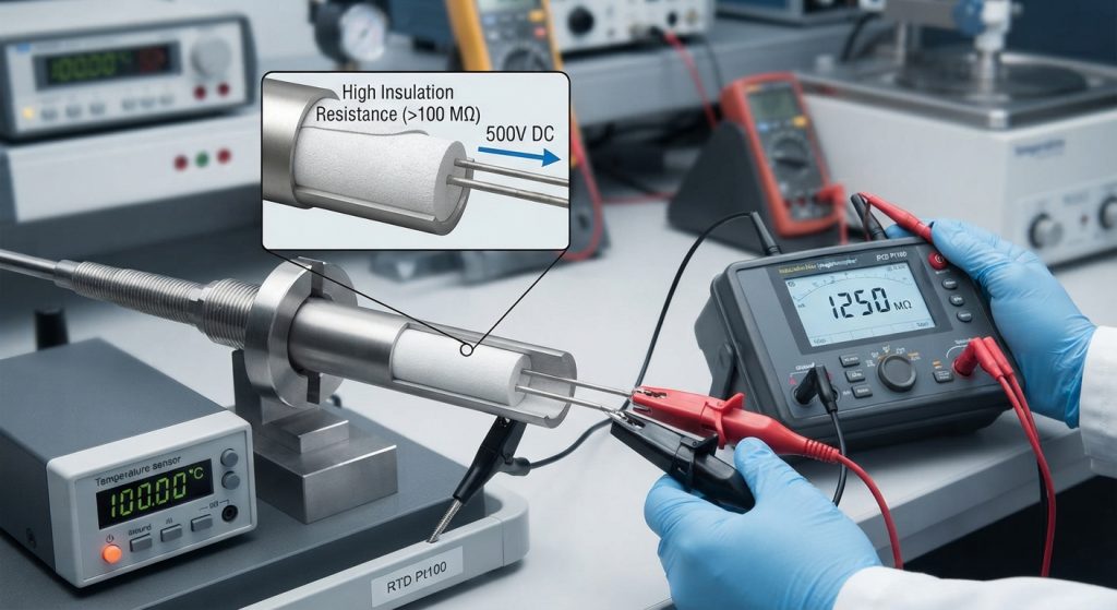
Insulation resistance is tested using a megohmmeter (insulation tester) that applies a standardized DC voltage.
- Test Conditions: The test is performed with the power off and the sensor disconnected from its transmitter. A voltage of 100 V DC or 500 V DC is typically applied between all short-circuited conductors and the metal sheath.
- Tolerance thresholds (according to industry standards):
- New sensor (at room temperature): The value must be greater than 100 MΩ
- Sensor in operation (at maximum operating temperature): The standard allows for a decrease in resistance, but ideally, it should not fall below 10 MΩ.
- Critical threshold: A value below 1 MΩ requires immediate replacement of the sensor, as measurement accuracy can no longer be guaranteed.
Conclusion
Insulation resistance is a key predictive health indicator for temperature sensors. Incorporating its systematic measurement into calibration and preventive maintenance programs allows you to anticipate failures, prevent unnoticed process drifts, and maintain high standards of geometric and thermal accuracy within your facilities.